Getting Started with ESP8266 Development on the Mac
I recently got interested in embedded development and trendy “IoT” applications. I really like the idea of low-cost and low-power devices, and with its built-in support for WIFI networking, the ESP8266 seems like a really compelling platform for experimenting with these kinds of device. It is a fully programmable SoC (albeit with limited programming options), and includes a full 802.11 wireless networking stack. And in deep sleep, the thing draws something like 7 microamps. Even when running, the device can be powered off coin cell batteries, so it fits the bill, on the low-power check box. The fact that you can pick up one of these things on AliExpress for $1.80 is pretty cool, too.
As a professional software developer, however, I don’t have any real experience with hardware, and only minimal experience with operating systems and interfaces with hardware. I have a few linux boxes I play around with, mostly VM images, but I wanted to do some development directly on the Macintosh.
So I’ve started this series of posts to describe my experience getting started with ESP8266 development on the Mac. I am trying to write them from the perspective of pretty much an complete n00b, so some parts of these posts might be entirely obvious to some readers. Other parts might presume knowledge of how networking and computers work, in general. When writing, it’s a fine line to divide, but hopefully it will be useful for someone who has started out like I did, basically from ground zero, but who maybe has some experience writing software and can otherwise follow simple instructions.
Update! Since writing this post, I have made some updates to my hardware and software. See the update sections, below.
DISCLAIMER: I am not an electrical engineer, and the steps I outline are not warranted for any fitness of purpose. They might work fine. They might burn your house down. Use at your own risk.
Helpful Information
One of sources of information I have found useful is Neil Koblan’s book on the ESP8266. Neil does a really good job of explaining the fundamentals of ESP8266 development (albeit somewhat biased towards Eclipse development), and I look forward to subsequent editions, as he publishes them. While you can download the book for free, I would urge anyone to pay something towards Neil’s hard work.
There are great forums and YouTube videos you can follow, as well. The key here is patience. If you’re like me, it takes reading and re-reading (or viewing and re-viewing) for things to sink in. And at least for me, this is a hobby; I have a day job, family, and assorted other responsibilities that take priority. I am not deluded into thinking it won’t take weeks or months to make significant progress.
I also have a friend who has helped coach me with getting started with this device and otherwise filling in my cavernous gaps when it comes to electronics. Thanks, Vlad!
Hardware
The first thing I had to do was sort out what hardware I needed in order to do any development. There are a lot of development boards out there that intend to be mostly plug and play, and I am interested in playing with some of them. See, for example, the NodeMCU or the WemosD1.
But my curiosity was really piqued by the very basic ESP-01, an ESP8266 board with just a few gpio pins. What I like about the board is its simplicity, even if it is less featured than the ESP-12, the current (at the time of writing) state of the art.
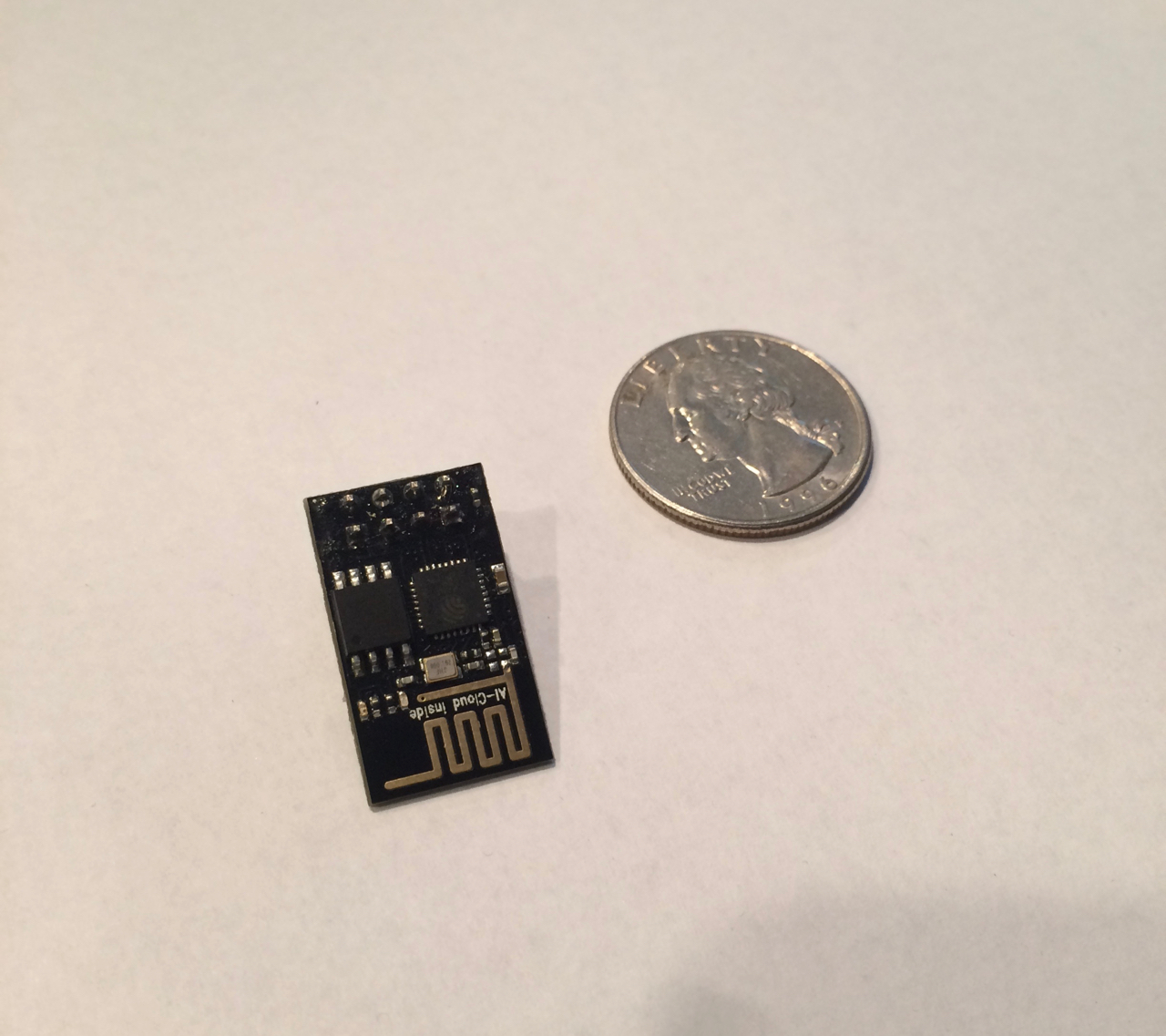
I was able to get two of these boards for $1.80 each, via Ali Express.
The ESP-01, unfortunately, is not breadboard-friendly. I did, however, find a nice little breadboard adapter, which has slots for the 4 pins that come out of the ESP-01. It also has a small capacitor, which Neil Koblan recommends, to handle load spikes.
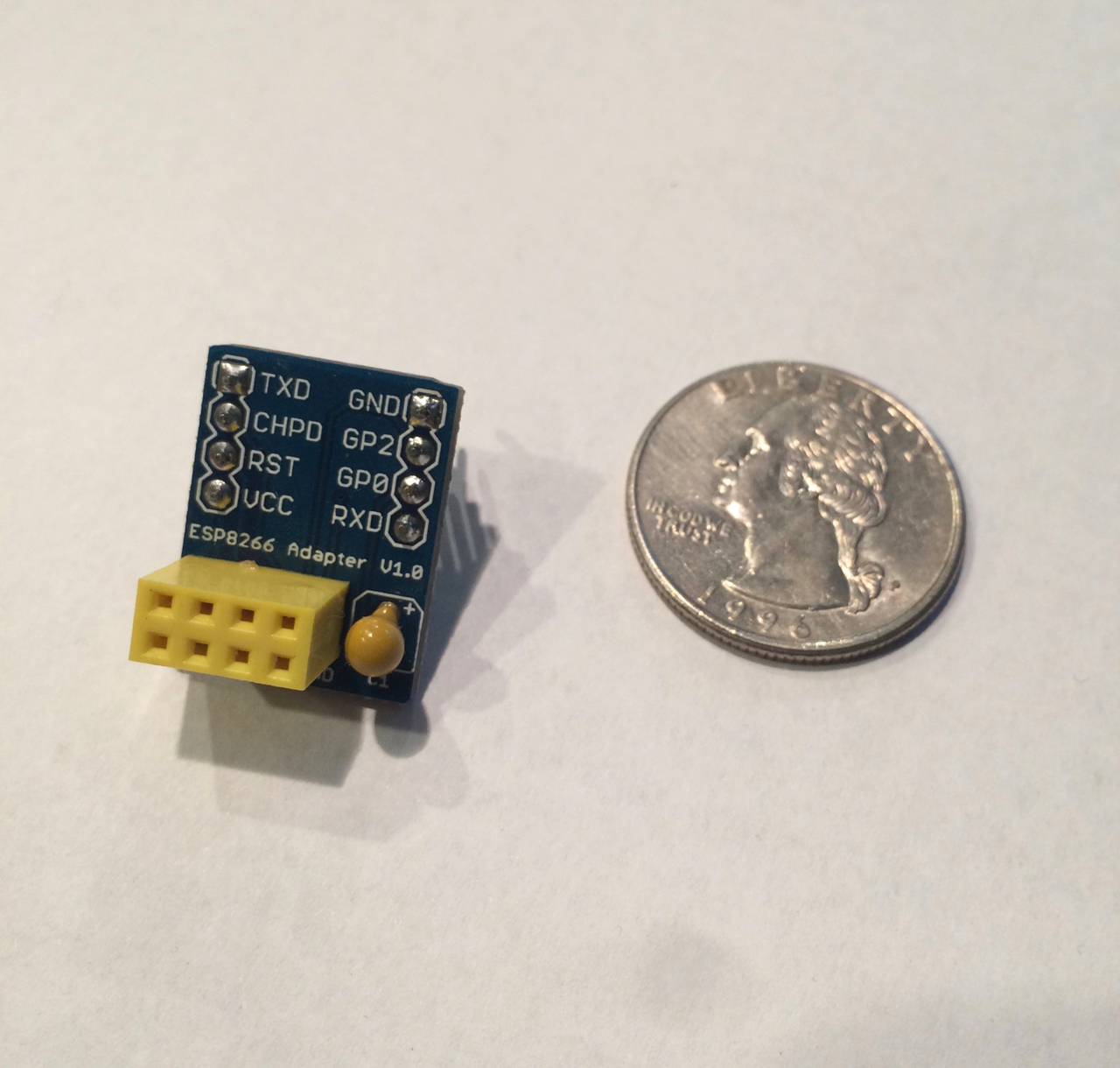
This adapter is not required – you can certainly make your own. But this one was convenient so I added it to my list.
Going with a basic ESP board requires that you provide a USB -> UART adapter, as the ESP-01 is not one one of those plug-and-play development boards. I chose an adapter based on the CP2102 chipset, as (I later discovered) there is good driver support on MacOS for this adapter:
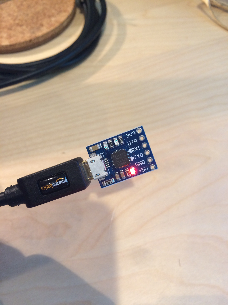
These boards come with pins that you’ll need to solder into the board. This allows the board to plug in directly to the breadboard. I accidentally inserted the board with these pins into the breadboard in the wrong position and ended up supplying 5v to the transmit pin on the ESP-01, which subsequently burned out the chip (I had bought two). I subsequently clipped the 5v pin, to make sure I didn’t make the same mistake in the future.
Note: The Wemos D1 has a built-in CH3400 chipset, for which there is a Mac OS kernel driver, but the support for this driver is unclear. Some of the versions of the driver are not signed, and the latest version I found was from some random internet site, and while the driver was claimed to have been signed, the package installer was not. I am sufficiently paranoid about running unsigned code in my kernel (root kit, anyone?) that I decided not to use MacOS to develop on this board. The Wemos board works out of the box on Linux, and I have played with that board on a VM, which I don't mind if it gets hacked or exploited. That's what VM snapshots are for, right?
Finally, I needed a power supply. The USB -> UART adapter will supply some current, but apparently not enough to reliably drive the ESP8266 chip. So an additional power supply is needed. I used a basic breadboard 3.3v/5v power supply, which you can easily source on Amazon or Ali Express.
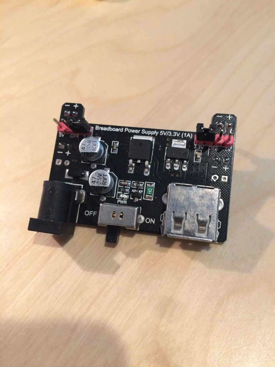
Make sure to only use 3.3v to the power strip on the breadboard, or you may fry your ESP chip (see above).
I also sourced a transformer for a direct supply of power from a wall socket, but you can also use a (male-male) USB cable. My Macbook Pro only has two USB ports, so I opted for the transformer.
I also got a bunch of male-male wires, and got a few short wires from a friend, which can reduce clutter on the board, but are not strictly necessary.
So the tally of hardware bits I needed were:
- A few standard 30-row breadboards.
- One (or more) ESP boards (ESP-01 or ESP-12, for example)
- (optional) A breadboard adapter, if you are using an ESP-01. You can also make your own with wires and optionally a capacitor.
- A USB -> UART adapter (I used one based off the CP2102 chipset, for compatibility with MacOS)
- A 3.3v power supply
- A bunch of male-male breadboard wires
- A mini-USB cable for my USB -> UART adapter (YMMV, depending on the board you select)
Everything above can be sourced for between $30 and $40 through Ali Express or Amazon. Ali Express is a lot cheaper, but delivery times can be very long. I even had to cancel one of my ESP-12 orders because the units never showed up. Amazon orders are fast, but comparatively expensive.
Assembly
There are numerous sources on the internet that describe how to wire up an ESP-01 board, including Neil Koblan’s book.
Here is a wiring diagram with the USB adapter and ESP-01 adapter I am using. If you are not using the same ESP-01 adapter or are using a different ESP board, then simply connect your wires to the corresponding pins on your ESP board. Note that the power supply is not shown on this diagram, but assume 3.3v applied to the positive rails on the bread board, with associated ground.
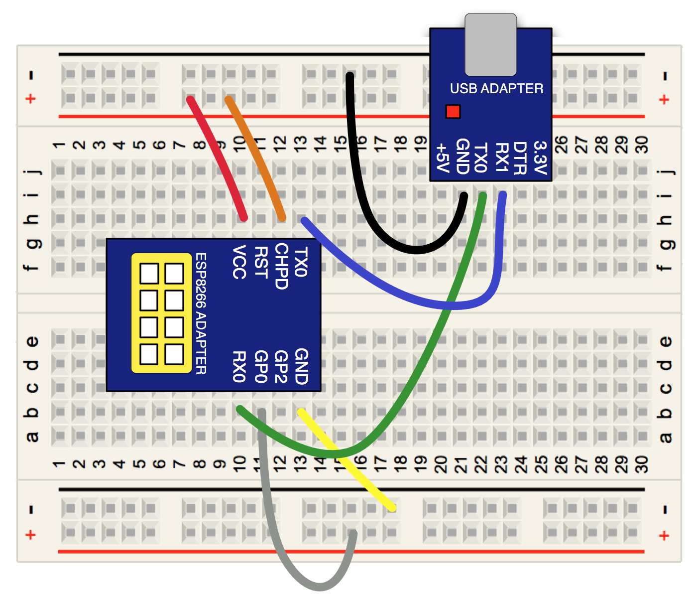
Instructions (you may use any colors you choose, obviously):
- Connect the USB adapter GND (ground) pin to the ground on your bread board. [black]
- Connect the USB adapter TX0 (transmit) pin to the RXD (receive) pin on the ESP8266. [green]
- Connect the USB adapter RX1 (receive) pin to the TXD (transmit) pin on the ESP8266. [blue]
- Connect the GND (ground) pin of the ESP8266 to the ground on your bread board. [yellow]
- Connect the VCC (voltage) pin of the ESP8266 to the positive rail (3.3v) on your bread board. [red]
- Connect the CHPD (?) pin of the ESP8266 to the positive rail (3.3v) on your bread board. [orange]
- Connect the GP0 pin of the ESP8266 to the positive rail (3.3v) on your bread board, in order to boot the device on power up. [gray] Note that you will connect this spin to ground when it comes time to image the device.
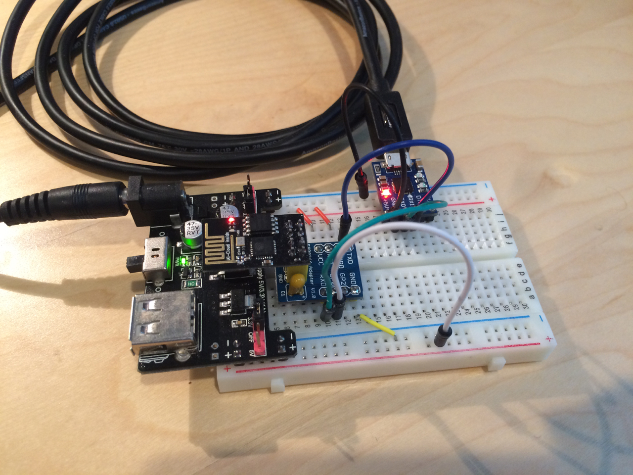
Fully assembled and powered up, my board looks like this:
Update! Since writing this post, I have moved to using an ESP-12 unit, which has more pins and supports some features that the ESP-01 does not (such as connecting pin 16 to RST, to allow the device to go into deep sleep mode). I had been having issues flashing the ESP-12 with earlier versions of micro python, but those issues seem to have resolved themselves since version 1.8.6 of the firmware.
Here is the ESP-12 unit, which I soldered to a breadboard-friendly adapter:
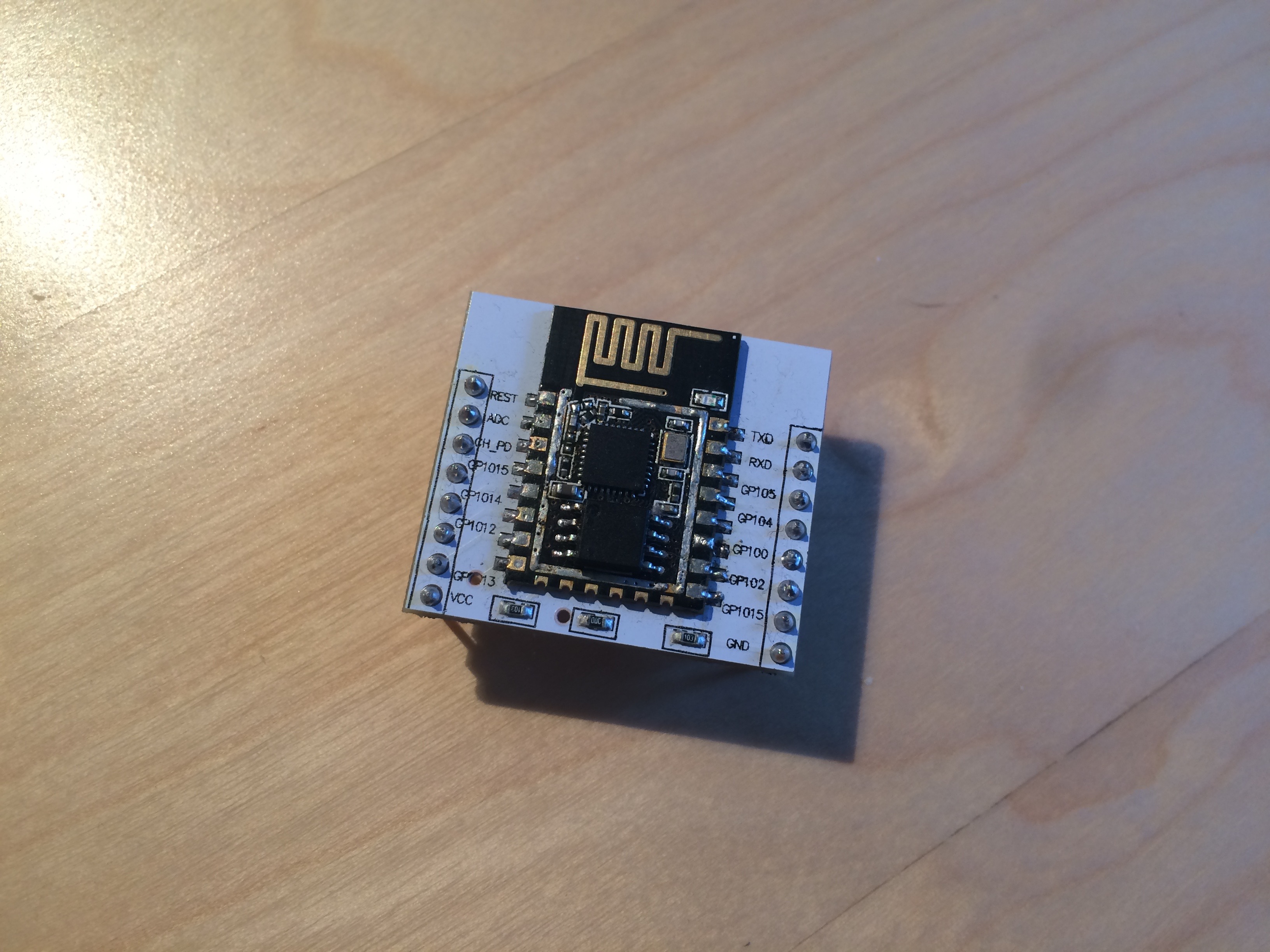
The ESP-12 normally has a shield over the ESP8266 and flash, for UL compliance. We removed this shield at one point to do surgery on the flash chip :) Note that GPIO16 is mislabeled “GPIO15” on this adapter.
And here is the ESP-12 on a breadboard, wired more or less as described above (except with a few extra inputs and outputs:
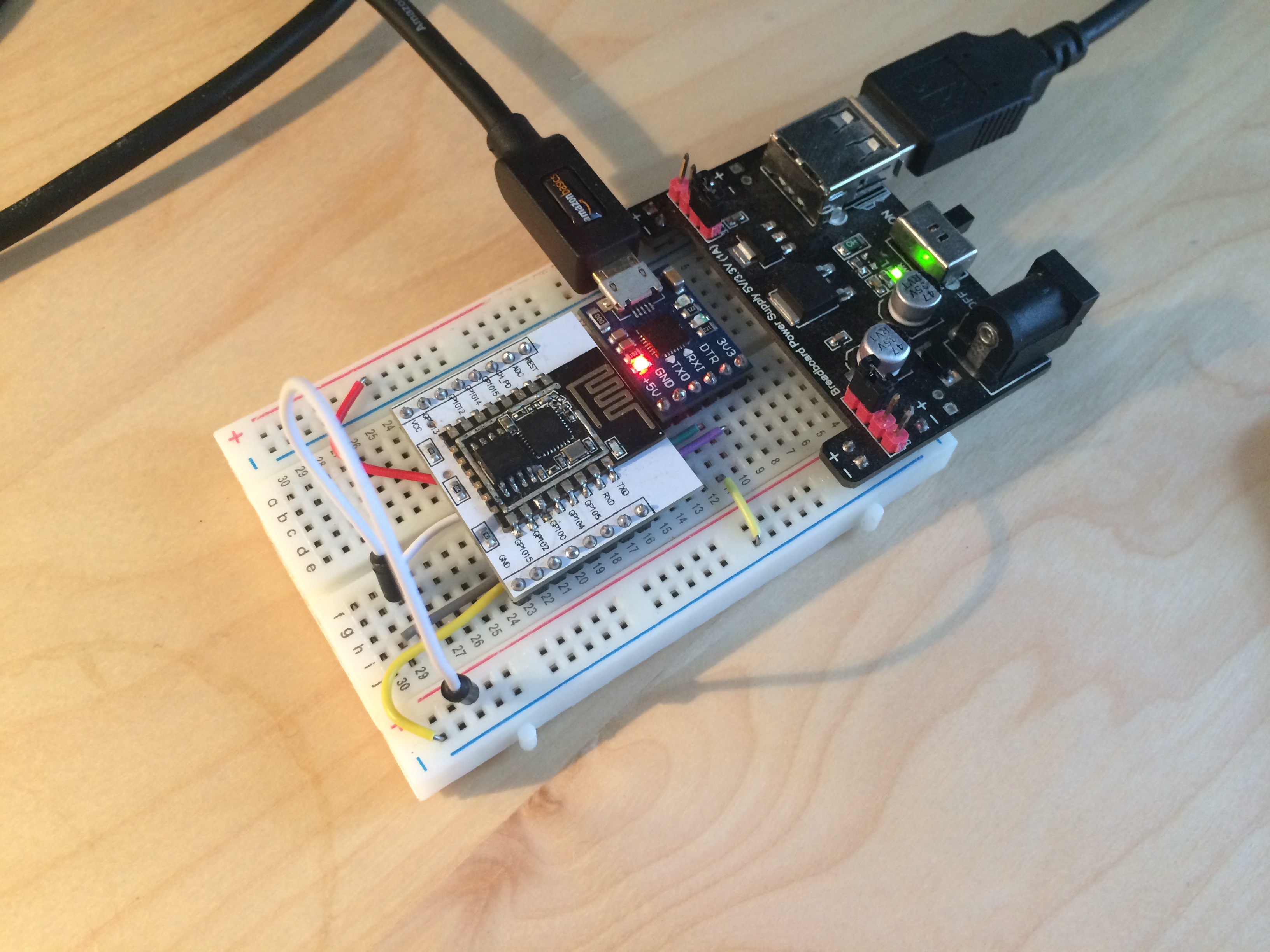
But don’t power it up just yet.
USB Driver
You’ll need to install a driver for the USB -> UART adapter, as one is not provided natively by Mac OS. I used the driver supplied by SILabs, which seems trustworthy enough; the drivers are signed, so at least Apple trusts them enough to issue a signing certificate.
Once the package is installed and you attach the USB adapter to a USB cable and port on your Mac (you don’t need to connect the adapter to your bread board), you should be able to see the /dev/tty.SLAB_USBtoUART/ device on your machine from within Terminal:
shell$ ls -l /dev/tty.SLAB_USBtoUART
crw-rw-rw- 1 root wheel 18, 4 Jul 13 19:46 /dev/tty.SLAB_USBtoUART
You can also verify the kernel module is loaded via the kextstat command:
shell$ kextstat | grep -i silabs
358 0 0xffffff7f83374000 0x6000 0x6000 com.silabs.driver.CP210xVCPDriver (4.10.11) CF83A369-EA70-3E24-B8FE-7351DCF03430
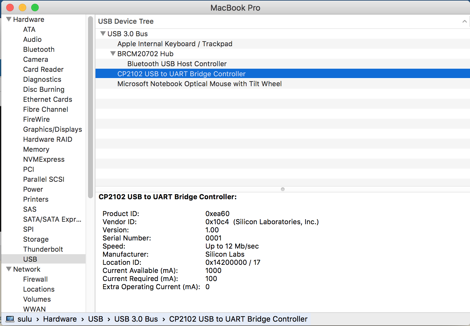
You should also be able to see the “CP2102 USB to UART Bridge Controller” under the USB tab in the System Information panel on your Mac:
Testing Your board using AT commands
The ESP8266 comes pre-configured with firmware that allows you to communicate over the USB-serial interface to the device, and send simple commands from the old and venerable AT command set, from the old days of modem communications. Establishing a connection with the ESP8266 and experimenting with these commands is a good way to verify that you have correctly set up your device.
First, you need a program on your Mac to communicate over the serial interface. I have seen some people using the screen utility, but I started out using minicom, a little command utility you can install via Homebrew.
Assuming you have brew installed,
shell$ brew install minicom
==> Downloading http://ftp.de.debian.org/debian/pool/main/m/minicom/minicom_2.7.orig.tar.gz
Already downloaded: /Library/Caches/Homebrew/minicom-2.7.tar.gz
==> ./configure --prefix=/usr/local/Cellar/minicom/2.7 --mandir=/usr/local/Cellar/minicom/2.7/share/man
==> make install
==> Caveats
Terminal Compatibility
======================
If minicom doesn't see the LANG variable, it will try to fallback to
make the layout more compatible, but uglier. Certain unsupported
encodings will completely render the UI useless, so if the UI looks
strange, try setting the following environment variable:

LANG="en_US.UTF-8"

Text Input Not Working
======================
Most development boards require Serial port setup -> Hardware Flow
Control to be set to "No" to input text.
==> Summary
🍺  /usr/local/Cellar/minicom/2.7: 16 files, 384K, built in 8 seconds
and you should be good to go.
Once you have brew installed, connect the USB->UART adapter to your USB port, but don’t turn on the power to the ESP8266 just yet.
In the shell, start up minicom, pointing it to the /dev/tty.SLAB_USBtoUART device:
shell$ sudo minicom -D /dev/tty.SLAB_USBtoUART
The screen will clear and you should see
Welcome to minicom 2.7

OPTIONS:
Compiled on Jun  8 2016, 16:10:27.
Port /dev/tty.SLAB_USBtoUART, 21:24:54

Press Meta-Z for help on special keys
You can now provide power to the ESP-01. The USB adapter LED should light up, and the blue LED on the ESP-01 should blink during boot and the red LED should stay on. On the mincom screen, you should see a little gobbleygook, and then:
l`{$?n't use rtc mem data
sd??b??
Ai-Thinker Technology Co.,Ltd.

ready
Congratulations! You can successfully booted and connected to your ESP8266!
As an initial test, enter AT, followed by the return key. You will then need to hit ctl-j, to send a line feed. You should get an ‘OK’ back from the ESP8266.
AT

OK
Note that you will always need to use thereturnandctl-jsequence when sending AT commands throughminicomin the remainder of the blog post.
Troubleshooting
Perhaps things did not go as smoothly for you as the above instructions. There are a few things to consider.
Does your ESP8266 have the correct firmware? If you are using a NodeMCU, Wemos, or equivalent board, your ESP8266 may come pre-configured with Lua or other firmware installed on the device. These instructions assume a pretty bare-bones, default AT command set firmware, which I get from the ESP-01 or ESP-12. If you are using a more developer-friendly board like the ones mentioned above, these instructions may not be for you.
Verify all of your wiring on your breadboard, and make sure your driver is installed and functioning as expected.
If you seem to be having issues with talking to the board via minicom, then you might need to adjust your connection settings in the mincom utility.
To get to a menu of commands, on MacOS you should use Meta-Z, which on Macintosh keyboards is usually esc-z.
+-------------------------------------------------------------------+
|                      Minicom Command Summary                      |
|                                                                   |
|               Commands can be called by Meta-key                  |
|                                                                   |
|               Main Functions                  Other Functions     |
|                                                                   |
| Dialing directory..D  run script (Go)....G | Clear Screen.......C |
| Send files.........S  Receive files......R | cOnfigure Minicom..O |
| comm Parameters....P  Add linefeed.......A | Suspend minicom....J |
| Capture on/off.....L  Hangup.............H | eXit and reset.....X |
| send break.........F  initialize Modem...M | Quit with no reset.Q |
| Terminal settings..T  run Kermit.........K | Cursor key mode....I |
| lineWrap on/off....W  local Echo on/off..E | Help screen........Z |
| Paste file.........Y  Timestamp toggle...N | scroll Back........B |
| Add Carriage Ret...U                                              |
|                                                                   |
|             Select function or press Enter for none.              |
+-------------------------------------------------------------------+
Your comm parameters are accessible via p. (Alternatively, meta-p if you are not in the command menu).
+---------[Comm Parameters]----------+
|                                    |
|     Current: 115200 8N1            |
| Speed            Parity      Data  |
| A:   next        L: None     S: 5  |
| B:   prev        M: Even     T: 6  |
| C:   9600        N: Odd      U: 7  |
| D:  38400        O: Mark     V: 8  |
| E: 115200        P: Space          |
|                                    |
| Stopbits                           |
| W: 1             Q: 8-N-1          |
| X: 2             R: 7-E-1          |
|                                    |
|                                    |
| Choice, or Enter to exit?          |
+------------------------------------+
Your settings should be 115200 for speed, 8 bits, no parity, and 1 stop bit (8-N-1)
I also found that I had to disable hardware flow control in my minicom configuration in order to get minicom to transmit to the serial port. Again, from with minicom, issue esc-z to get the help menu, and then type ‘o’ to configure minicom. You should see:
+-----[configuration]------+
| Filenames and paths      |
| File transfer protocols  |
| Serial port setup        |
| Modem and dialing        |
| Screen and keyboard      |
| Save setup as dfl        |
| Save setup as..          |
| Exit                     |
+--------------------------+
Arrow down to “Serial port setup” and hit enter:
+-----------------------------------------------------------------------+
| A -    Serial Device      : /dev/tty.SLAB_USBtoUART                   |
| B - Lockfile Location     : /usr/local/Cellar/minicom/2.7/var         |
| C -   Callin Program      :                                           |
| D -  Callout Program      :                                           |
| E -    Bps/Par/Bits       : 115200 8N1                                |
| F - Hardware Flow Control : Yes                                       |
| G - Software Flow Control : No                                        |
|                                                                       |
|    Change which setting?                                              |
+-----------------------------------------------------------------------+
Select ‘F’ and it should toggle to “No”. Hit enter to return to the configuration menu. Then arrow down to “Save setup as df1” to save your changes. You may then arrow down to exit to return.
AT Commands
The AT command set supported by the ESP8266 is documented by Espressif, the manufacturer, and is available form their documents page.
We’ll walk through a few useful commands here, just to get a sense of what you can do. The initial set will be read-only commands, in that they will not affect the state of your ESP8266. We will then move to commands that mutate the state of your device, but which are not saved to flash memory. Finally, we will experiment with commands that changes the state of the device and writes to flash and are preserved for reboot.
First, let’s get some information from the ESP8266 using the AT+GMR command (remember to always hit return, and then ctl-j):
AT+GMR
AT version:0.40.0.0(Aug  8 2015 14:45:58)
SDK version:1.3.0
Ai-Thinker Technology Co.,Ltd.
Build:1.3.0.2 Sep 11 2015 11:48:04
OK
You can ask what wireless mode the device is in by using the AT+CWMODE_CUR? command:
AT+CWMODE_CUR?
+CWMODE_CUR:2

OK
2 indicates “softAP mode”, which means the device is functioning as a wireless access point, much like your router.
You can see this network by running the airport command on MacOS, which is kind of buried deep in Apple’s 802.11 framework:
shell$ /System/Library/PrivateFrameworks/Apple80211.framework/Versions/Current/Resources/airport -s
                            SSID BSSID             RSSI CHANNEL HT CC SECURITY (auth/unicast/group)
                            SSID BSSID             RSSI CHANNEL HT CC SECURITY (auth/unicast/group)
             MyWirelessNetwork 48:5d:36:76:d6:ee -84  132     Y  US WPA2(PSK/AES/AES)
             MyNeighborsWirelessNetwork 90:84:0d:e0:bc:2c -42  149,+1  Y  US WPA(PSK/TKIP/TKIP) WPA2(PSK/AES,TKIP/TKIP)
             MyNeighborsWirelessNetwork 90:84:0d:e0:bc:2b -31  11      Y  US WPA(PSK/TKIP/TKIP) WPA2(PSK/AES,TKIP/TKIP)
             MyWirelessNetwork 48:5d:36:76:d6:f0 -74  1       Y  US WPA2(PSK/AES/AES)
             AI-THINKER_DE1ECE 1a:fe:34:de:1e:ce -30  1       N  -- NONE
As you can see, the AI-THINKER_DE1ECE network shows up in the list.
You can also see this network in the Wifi menu on your Mac:

As you can see, AI-THINKER_DE1ECE shows up as an unprotected network.
Now let’s run some commands that change the state of the device. These instructions are based off the Expressive ESP8266 AT Command Examples document, adapted to use the non-deprecated APIs and for interfacing with MacOS.
We can change the mode the ESP8266 is operating in to include station mode, as well.
AT+CWMODE_CUR=3

OK
This way, the ESP8266 can function both as a wireless access point (like your wireless router, as described above), and as a wireless client. (If you set the wireless mode to 1, the ESP8266 will only operate in station mode.)
Once you are in station mode, you can list the available access points, from the point of view of the ESP8266, using the AT+CWLAP command:
AT+CWLAP
+CWLAP:(3,"MyWirelessNetwork",-84,"48:5d:36:76:d6:f0",1,-16)
+CWLAP:(4,"MyNeighborsWirelessNetwork",-34,"90:84:0d:e0:bc:2b",11,-39)

OK
You can connect to one of these networks using the AT+CWJAP_CUR command, supplying the wireless network name and password (if applicable). Note that it may take a few seconds to connect and get an IP.
AT+CWJAP_CUR="MyWirelessNetwork","XXXXXXXXXXX"
WIFI CONNECTED
WIFI GOT IP

OK
Now that you are connected, you can get the ESP8266’s IP address using the AT+CIFSR command:
AT+CIFSR
+CIFSR:APIP,"192.168.4.1"
+CIFSR:APMAC,"1a:fe:34:de:1e:ce"
+CIFSR:STAIP,"192.168.1.178"
+CIFSR:STAMAC,"18:fe:34:de:1e:ce"

OK
The STAIP field contains the IP address of the ESP8266.
You should then be able to ping the device at this address from your Mac:
shell$ ping -c 10 192.168.1.178
PING 192.168.1.178 (192.168.1.178): 56 data bytes
64 bytes from 192.168.1.178: icmp_seq=0 ttl=255 time=2.281 ms
64 bytes from 192.168.1.178: icmp_seq=1 ttl=255 time=2.436 ms
64 bytes from 192.168.1.178: icmp_seq=2 ttl=255 time=2.545 ms
64 bytes from 192.168.1.178: icmp_seq=3 ttl=255 time=9.055 ms
64 bytes from 192.168.1.178: icmp_seq=4 ttl=255 time=11.121 ms
64 bytes from 192.168.1.178: icmp_seq=5 ttl=255 time=2.562 ms
64 bytes from 192.168.1.178: icmp_seq=6 ttl=255 time=2.610 ms
64 bytes from 192.168.1.178: icmp_seq=7 ttl=255 time=2.362 ms
64 bytes from 192.168.1.178: icmp_seq=8 ttl=255 time=15.415 ms
64 bytes from 192.168.1.178: icmp_seq=9 ttl=255 time=2.239 ms

--- 192.168.1.178 ping statistics ---
10 packets transmitted, 10 packets received, 0.0% packet loss
round-trip min/avg/max/stddev = 2.239/5.263/15.415/4.560 ms
Some AT commands allow you to send data through the ESP8266 wireless network. In order to do that easily, we need a program that listens on your network for data. I like to use the netcat utility for this, which also can be installed on the Mac via brew:
shell$ brew install netcat
The netcat command can listen on a network interface and port using tcp (the default) or udp, but let’s use the default (tcp) for simplicity. This command (which you can run in a separate Terminal window) will start netcat and listen on port 44404, waiting for connections from remote clients.
Note: You will need to temporarily disable the firewall on MacOS in order to proceed with these instructions, as well will be telling the ESP8266 to connect to your netcat server wirelessly over TCP/IP. If your firewall is enabled, the connection from the ESP8266 will be blocked. You should only turn off your firewall on a trusted network, and turn it back on after experimenting with the ESP8266. Advanced users may wish to configure the firewall on MacOS to only allow incoming TCP connections from the netcat application.
shell$ netcat -l -p 44404
You should determine your IP address via the “System Preferences” panel for via ifconfig, e.g.,
shell$ ifconfig
...
en0: flags=8863<UP,BROADCAST,SMART,RUNNING,SIMPLEX,MULTICAST> mtu 1500
	ether 6c:40:08:9b:ef:4e
	inet6 fe80::6e40:8ff:fe9b:ef4e%en0 prefixlen 64 scopeid 0x4
	inet 192.168.1.154 netmask 0xffffff00 broadcast 192.168.1.255
	nd6 options=1
	media: autoselect
	status: active
...
Here, the IP address of my Mac is 192.168.1.154.
Back in your minicom window, you can establish a connection to your netcat listener via the AT+CIPSTART command. Specify the protocol (tcp), the IP address, and port on which your netcat server is listening.
AT+CIPSTART="TCP","192.168.1.154",44404
CONNECT

OK
Back in your netcat window, you should see:
Connection from 192.168.1.178:14981
You can get information about this connection via the AT+CIPSTATUS command:
AT+CIPSTATUS
STATUS:3
+CIPSTATUS:0,"TCP","192.168.1.154",44404,0

OK
This tells us that connection ID 0 is currently connected via tcp to port 44404 on host 192.168.1.154 as a client.
You can then send some data over this TCP connection using the AT+CIPSEND command. Specify the number of bytes to send (in this case, 5). You will be prompted for data, and type in the characters “hello” (without the quotes).
AT+CIPSEND=5

OK
>
Recv 5 bytes

SEND OK
Back in your netcat window, you should see “hello” printed to the screen.
You can close the connection via the AT+CIPCLOSE command:
AT+CIPCLOSE
CLOSED

OK
The netcat application in the other window should then terminate.
Congratulations. You have just sent some data from your ESP8266 to your Mac using the wireless network!
Finally, let’s use some AT commands to change the configuration on the flash storage on the ESP8266, and restart the device, making sure that the settings “stick”.
Back when we connected to the local wireless network, we changed only the current settings on the device, not the settings as they are read off flash storage when the ESP8266 boots. We can change these settings using the *_DEF AT commands.
Let’s set the default wireless mode to be both a wireless client and server:
AT+CWMODE_DEF=3

OK
And in addition, let’s set the default network on the device.
AT+CWJAP_DEF="MyWirelessNetwork","XXXXXXXXXXX"
WIFI CONNECTED
WIFI GOT IP

OK
WARNING: This command will store the password of your wireless network on your ESP8266, possibly in a way that makes the password available to attackers. Do not perform this step if you are uncomfortable with this risk.
You should now be able to restart the device, either by powering down and powering back up the device, or by issuing the AT+RST command:
AT+RST

OK
WIFI DISCONNECT

 ets Jan  8 2013,rst cause:2, boot mode:(3,6)

load 0x40100000, len 1396, room 16
tail 4
chksum 0x89
load 0x3ffe8000, len 776, room 4
tail 4
chksum 0xe8
load 0x3ffe8308, len 540, room 4
tail 8
chksum 0xc0
csum 0xc0

2nd boot version : 1.4(b1)
  SPI Speed      : 40MHz
  SPI Mode       : DIO
  SPI Flash Size & Map: 8Mbit(512KB+512KB)
jump to run user1 @ 1000

?n't use rtc mem data
{l?b??
Ai-Thinker Technology Co.,Ltd.

ready
WIFI CONNECTED
WIFI GOT IP
Again, you can run the AT+CIFSR command to verify that you are connected to the local network:
AT+CIFSR
+CIFSR:APIP,"192.168.4.1"
+CIFSR:APMAC,"1a:fe:34:de:1e:ce"
+CIFSR:STAIP,"192.168.1.178"
+CIFSR:STAMAC,"18:fe:34:de:1e:ce"

OK
Your ESP8266 now automatically connects to your wireless network on boot.
If you are uncomfortable with your wireless network password being stored on the flash module of your ESP8266, you can restore your ESP8266 to its factory settings via the AT+RESTORE command:
AT+RESTORE
d?c$`{$|????rnoN???|?l`
Ai-Thinker Technology Co.,Ltd.
ready
Note: For the truly paranoid, it's likely that your password could still be retrieved by some one (or some three lettered agency), as I suspect it is unlikely that password data is overwritten enough times to not be recoverable by a team of forensic scientists. So take whatever precaution you deem necessary.
Don’t forget to turn your Mac’s firewall back on!
Next Time
These instructions give you enough information to get started connecting your ESP8266 to the Mac and sending simple AT commands over a serial interface. Take a look at the Espressif AT Command Set documentation, and experiment with other commands, such as using UDP as a protocol.
Using AT commands, of course, is not what the ESP8266 is all about. It’s really about programming the device, and making cool “IoT” applications. There are lots of ways to do that. So next time, I’ll talk about loading images and using Micro Python to drive your ESP8266 through the python shell. Stay tuned!
Copyright (c) 2016 dushin.net This work is licensed under a Creative Commons Attribution 4.0 International License.

Comments
Because of the prevalence of automated spam on the internet, I turn off comments on my blog posts. If you have comments or questions about this, please send me email using first-name -at- last-name -dot- net, where you can find my first and last name in the About page of this blog.