Solar Powered ESP32
If blinking an LED is the “Hello, World!” of the Internet of Things, then building a weather station runs a close second. Maybe it’s analogous to “writing your first class”, or perhaps it’s up there with learning how to use java.net.Socket.
And while integrating a temperature sensor with a micro-controller gives one a well-deserved sense of accomplishment, I have always been a little disappointed with the various Getting Started tutorials you can find on the internet on such topics, finding them silent about the steps it would take to actually build a weather station and let it sit out in, well, the weather, far away from a continuous source of electricity.
Like many people, I am also starting to gain and interest in, and an appreciation for, the engineering that is demanded out of so called “green” energy. While reducing our carbon footprint is a critical goal we need to reach, there are significant challenges in converting our consumption of energy to using renewable sources. The technology is certainly evolving, and I think it is incumbent on us, as engineers, to try to understand and, if possible, improve on any discoveries and developments.
So, I started a little research project to try to understand how to build a self-sustaining, battery powered, and solar charged circuit to drive an Espressif ESP32. An actual weather station can come later. What I wanted to do first was to understand what it would take to build an ESP32-based device that is going to be outside for a long period of time, away from a constant power source.
In thinking about such a a circuit, I was after a few things:
- The circuit should not require charging from a wall socket, for at least an appreciable duration (at least a month or more);
- It should be capable of operating in a range of conditions, including wet, hot, cold, and dry;
- The ESP32 could make use of deep sleep, drawing little if any power during its sleep periods;
- However, when awake, the ESP32 should be able to connect over WiFi to send measurements, check in with home, and so forth;
- The circuit should be as efficient as possible;
- It should be safe (no fires!);
- It should be small, so it can fit in a small box;
- It should be cheap to make/build.
With these requirements, I set out on a very fun and interesting journey to try to find a workable solution, and I am happy to say that I came up with something that seems to work fairly well, which I describe below in this blog post. I won’t say that it is the best solution out there, or that it can’t be improved upon. (That’s kind of the “log” part of this ‘blog.) But it does seem to work.
I should note that this blog post comes with the usual disclaimers. The author provides no warranty of suitability or fitness of purpose. Please exercise care and caution when working with electronic components, especially with lithium batteries.
Note. As it will be evident, I am not trained professionally in electrical engineering. So I am not offended in the least if you take most of what I write with extreme skepticism. If you do find egregious (or just plain stupid) mistakes, please let me know. See the bottom of the page for contact information.
Power Requirements
Even at 3.3v, the ESP32 is not exactly a power-efficient device, at least when using the on-board radio for WiFi or Bluetooth. WiFi seems to drain around 130mA, even at idle, and even more current will be drawn during radio initialization and while sending or receiving data. At that rate, you are lucky to get a few hours out of a 600mAh battery, so running an ESP32 full time on a battery is pretty much out of the question.
Luckily, the ESP32 supports a number of sleep modes, including deep sleep, which draws only in the low 10s of micro-amps. And I am perfectly happy with long periods of sleep, for the “external” applications I currently have in mind.
So for the purposes of this experiment, I am going to assume sleep intervals of between 1 and 10 minutes. The idea is that the ESP32 will sleep for some time interval. It will then wake, take some measurements, and then fire up WiFi and send the measurements to some listening service. It will then go back into deep sleep, to repeat the same logic. We’ll leave the details about servers and protocols to some other blog post. For now, just assume having a WiFi connection is enough.
In this case, we expect the Wifi radio to be on for only around 5-10 seconds every period, which should give us plenty of runway for even a relatively low capacity battery.
The ESP32 supports a limited subset operations during sleep using the Ultra Low Power (ULP) co-processor on the device. I am interested in experimenting with this feature, especially because the Analog to Digital Converter (ADC) and I2C interfaces are usable in deep sleep. For example, you might be able to program the ULP processor to monitor the voltage while in sleep mode, and only wake the device if there is sufficient power coming from the battery; otherwise, wait a little longer for the battery to charge. A future blog post, perhaps. But for now, assume the ESP32 is in deep sleep, doing nothing for those 10 minutes.
Another thing I found important was to use as close to a bare-bones ESP32 as possible. While you can buy development boards for ESP32s that contain mini-USB connectors, UART controllers, 5v voltage regulators, status LEDs, and so forth, it is unclear how much drain these extra components add to a system.
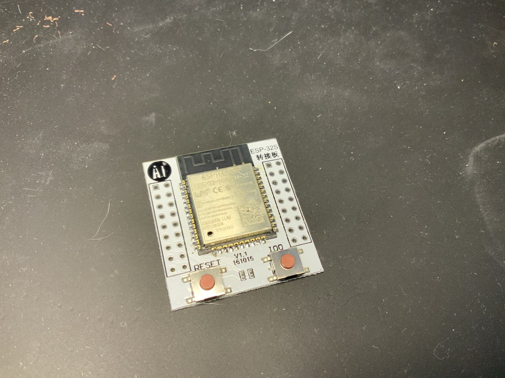
For these experiments, I am using an ESP32 WROOM module, connected to a little breakout board that has buttons for RESET (rebooting the device), as well as a button to pull IO0 low (press IO0 and RESET to flash). This board adds minimal circuitry to a bare ESP32 module, which gives me some confidence that I am not loosing power to some unknown component.
Solar Panels
Solar panels are fairly easy to come by at an affordable price on Amazon, Ali Express, or the like. For someone like me, it is hard to judge the quality of these cheap panels, and in most cases, the advertised power output is not exactly what I have seen in real world testing.
Still, I have found that 5.5v and 6v panels seem to provide enough power to charge the batteries I am using to power the ESP32. So I am conducting experiments with a single 6v 1w panel (ostensibly 166mA, but nowhere near that shorted in direct sun), a single 6v 2w panel, and four 80mA 5.5v panels (connected in parallel). I am primarily interested in finding the smallest panel that would fit over a small plastic box, but would also provide enough power to bring a battery up to charge on a sunny day.
For reasons explained more below, an important part of working with solar panels is to find their maximum power point. This is the point on the Current-Voltage (IV) graph for the panel where the power (I * V) reaches a maximum (strictly, where the derivative of the power curve is 0). For example, here is a graph of the current (blue) and power (green), as a function of voltage, for one of the 6v panels I bought:
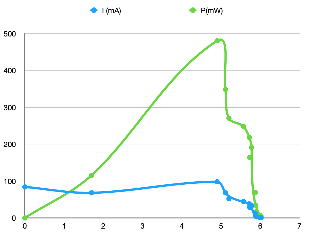
As you can see, the power hits a maximum at around 5.2 volts. I think if this as the voltage whereby the solar panel can push as much current with as much force as possible, and it will become important when designing our circuit, below.
Batteries
I had read a nicely written tutorial on RandomNerdTutorials, explaining how to power an ESP32 using 4.2v 18650 Lithium Ion battery, and to simultaneously charge the battery using a TP4056 charging module, which can be had for short change on Amazon. I could kind of get this to work, but I found that the ESP32 would have difficulty booting, suggesting perhaps the battery was unable to provide sufficient current through the low voltage regulator.
So I was interested in finding an alternative to 4.2v lithium ion batteries, and fortunately, there is an alternative that is ideally suited for 3.3v applications like the ESP32 – Lithium Iron Phosphate (LiFePo4) batteries, which are starting to show up a lot in solar applications. Since most LiFePo4 cells are already 3.2v, no voltage regulators are necessary, which can save power in a power-critical application.
LiFePo4 batteries have some advantages over Lithium Ion batteries, including the following:
- LiFePo4 batteries support more up to 4 times as many charge cycles compared to their Lithium Ion counterparts;
- LiFePo4 batteries have a more stable chemistry and are less prone to fire than Lithium Ion batteries;
- LiFePo4 batteries are safer for the environment, as they do not contain cobalt;
- LiFePo4 batteries have nearly constant discharge voltage until they reach a state of discharge, which can provide a stable source of voltage for an ESP32, which can only operate in a limited voltage range.
- For 3.3v applications like the ESP32, they do not require voltage regulation to power the device, so at least in this case, they are far more efficient than using conventional 4.2v Lithium Ion technology.
LiFePo4 batteries come in various form factors and capacities, ranging from 14430 (sub-AA, typically found in those outdoor solar lights), 14505 (AA), 18650, and above. AA form-factor batteries tend to have around 600mAh of capacity, but I have found that they do have a hard time providing enough current to start the WiFi radio subsystem when the voltage drops below 3.4v.
Another option would be to run multiple AA cells in parallel, but I found some 3.2v 18650 LiFePo4 batteries for a decent price, which claims 1.5Ah of capacity. The 18650 size was just fine for the application I was thinking of, and these batteries seem to provide enough current for the ESP32 around the clock. So my experiments are mostly based around that battery cell.
Charging Circuit
I wanted to find a method of charging an LiFePo4 battery from a Solar panel, and fortunately, on Hackaday.io, Patrick Van Oosterwijck has designed a complete charging board for a wide range of solar panels (4v-28v) and a wide range of battery packs (up to 3A!).
If you are interested in stopping here and just buying a charging board that works, I encourage you to support Patrick and buy one of his boards off his Tindie site. His boards are more full-featured that what I am going to describe here, but I can attest that they work out of the box (with a little soldering).
I am interested in a slightly more special purpose board – one that is suited for the ESP32 and a small single-cell 3.2v battery (Patrick’s board also has support for over-heat and under-heat protection, an important feature I have not added to my board.)
At the center of Patrick’s design is the Consonance CN3801, an integrated circuit that is designed specifically for charging LiFePo4 batteries using solar panels. US/domestic parts supplies (mouser, digikey, etc) don’t seem to carry these chips, but I was able to find some on Ali Express for around $0.48 a piece (plus shipping). They took around 6 weeks to arrive, and most of the time seems to have been spent in US customs. Perhaps they had suspicious packaging, or maybe they needed to run my address through an FBI database. Who knows.
The CN3801 data sheet includes a “typical circuit”, which I used to base my design, along with Patrick’s which he has open sourced.
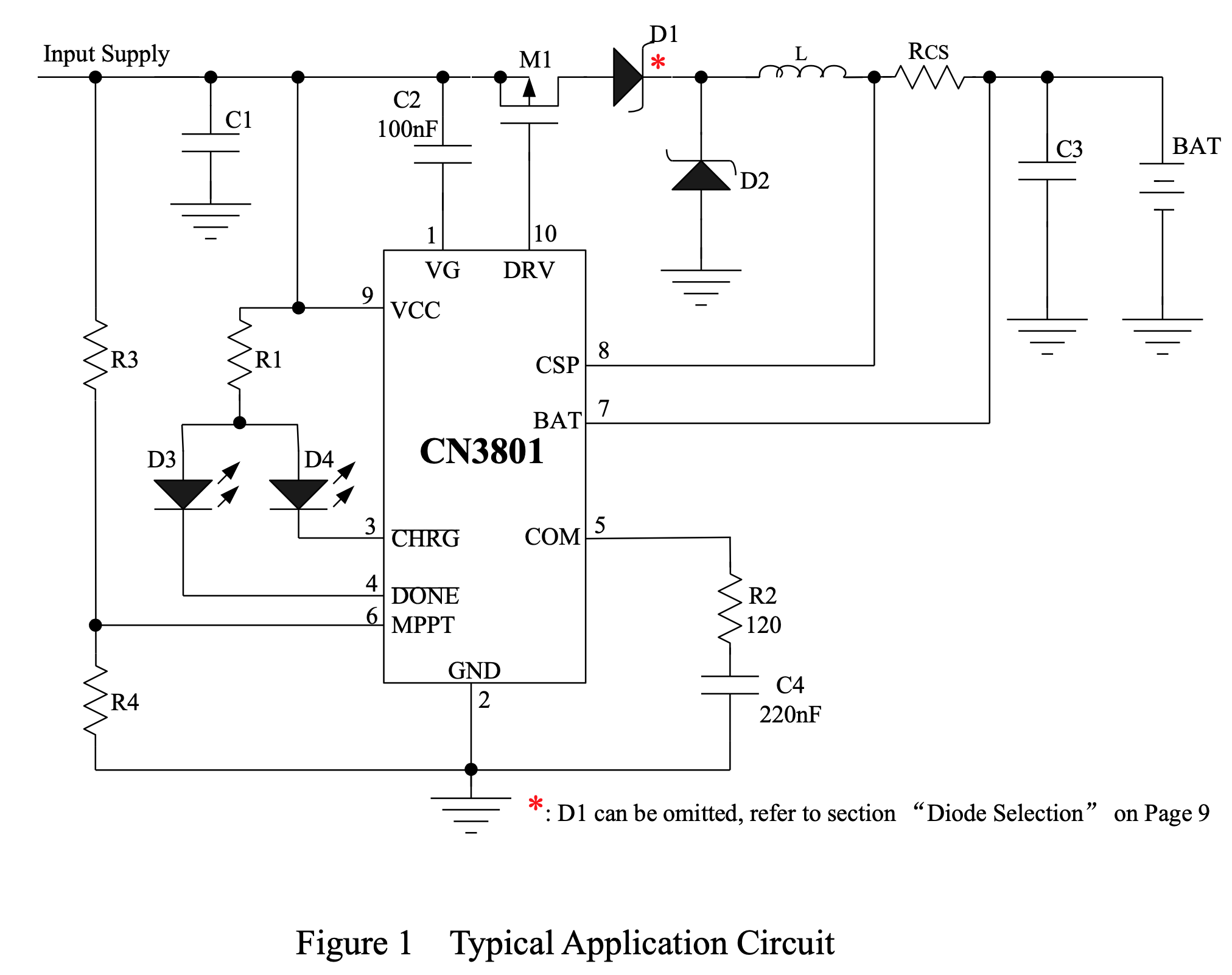
There are two “programmable” parts of this circuit:
- The voltage divider used for the MPPT input pin (6) on the CN3801; the divider controls the conditions under which the CN3801 will begin a charge cycle and deliver current to the battery; and
- The current sense resistor (Rcs) between the output CSP pin (8) and BAT pin (7); this resistor sets the maximum current to charge the battery, to prevent over charging.
The voltage divider is designed to input 1.205v to the MPPT pin when the solar panel is at its maximum power point. In my case, I set the pair of resistors to output 1.205v when the solar panel is outputting 5.2v.
The size of the current sense resistor is based off an internal 120mV reference, and in my case I set the current sense resistor to cap the maximum current at 500mA, which called for a 0.24 ohm resistor. I could probably go higher than 500mA, but I have yet to see a solar panel in the size I am willing to use that will put out more than 100mA, in direct sun (running downhill in a hurricane), even shorted.
Powering the ESP32
The ESP32 can be a finnicky device, especially in low power situations, and especially when there is a large current draw when firing up the WiFi radio. Brownouts are not uncommon, if there is insufficient power, and a circuit (and accompanying software) that may run unattended for days or months needs to be able to accommodate these scenarios.
The ESP32 is powered off the output battery circuit, but it is controlled by an active-low voltage supervisor, which, when the battery voltage drops below a certain level (3.0v, in my experiments), will pull the EN(able) pin low on the ESP, and subsequently cut off power to the ESP32. The basic idea is that we do not want to run the battery flat if, for some reason, we can’t come up with enough power to start the ESP32. Instead, the circuit should shut down power to the ESP32 until it has charged to a sufficient voltage.
Reading Battery Voltage
I am reading battery voltage using the ESP32’s on-board analog-to-digital converter (ADC), using 12-bit resolution and attenuated to 0-1.1v using a voltage divider on the battery power circuit.
I did find that it is essential to perform any ADC measurements on the ESP32 before starting the WiFi radio, as RF interference can introduce significant noise to the readings. I also added a small capacitor to the voltage divider, for better accuracy under power fluctuation.
Prototype Board
KiCad drawings for this circuit are available from my solar-esp32 Github repository. You can order 3 copies of this board (without components) on OshPark for $5.
Here is a 3d rendering of side 1 of this circuit, which contains the bulk of the charging components:
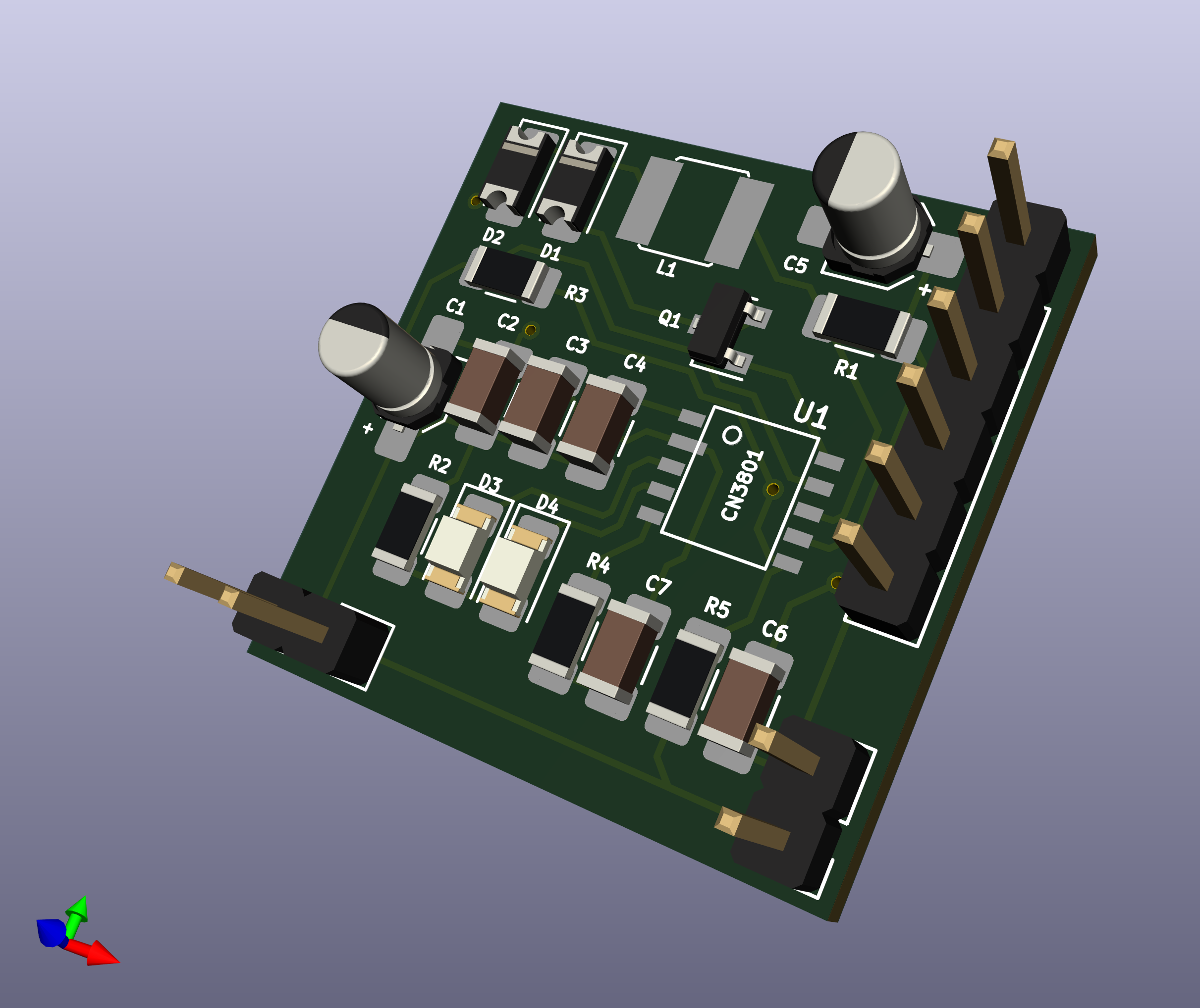
Side 2 contains the additional goodies for the ESP32, including the voltage supervisor described above, the voltage divider for reading battery voltage, a 10 uF capacitor to smooth out any voltage drops, and a status LED (for convenience), so that I can provide some indication of what state the device is in:
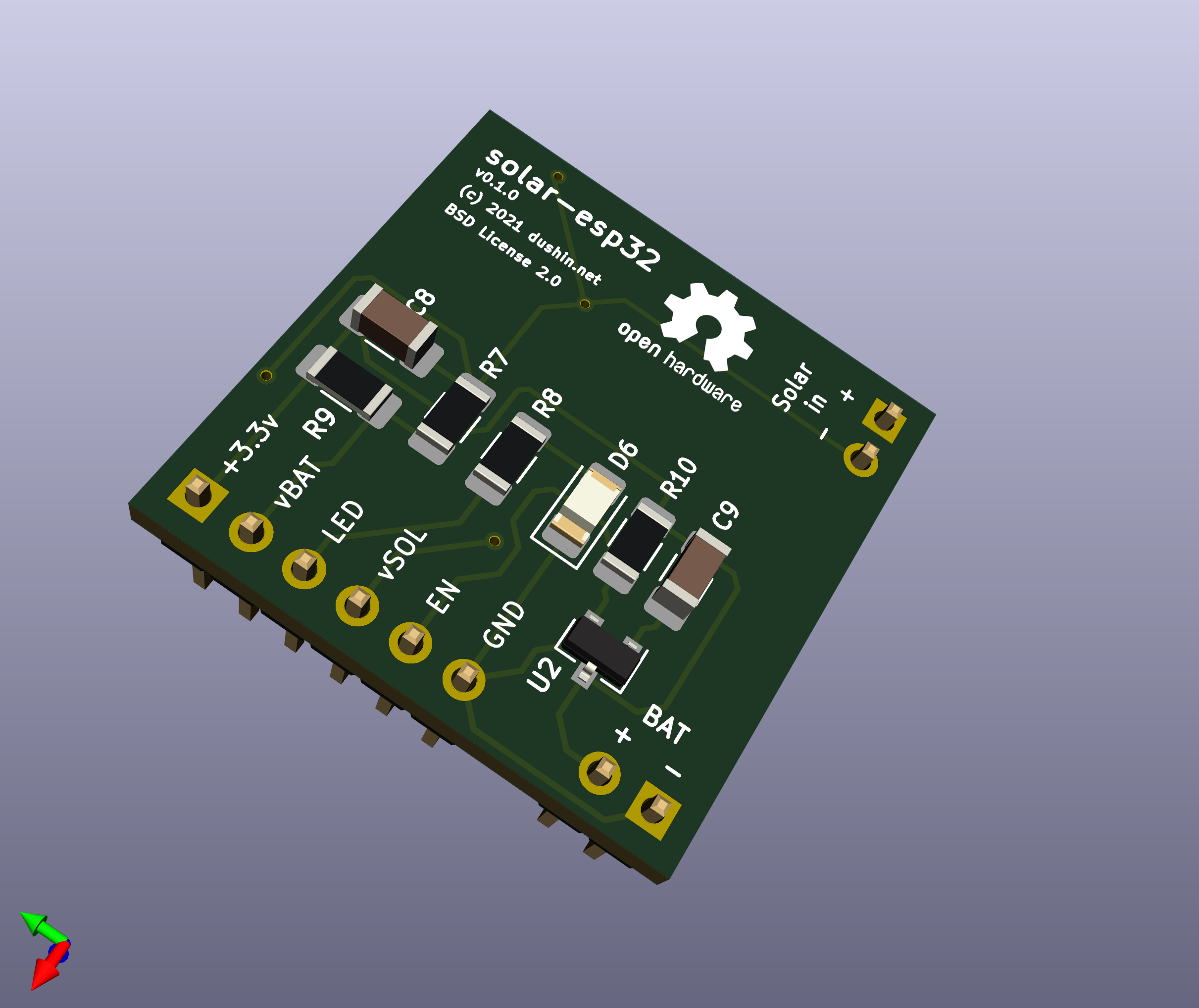
The board fits on a 1” x 1” PCB.
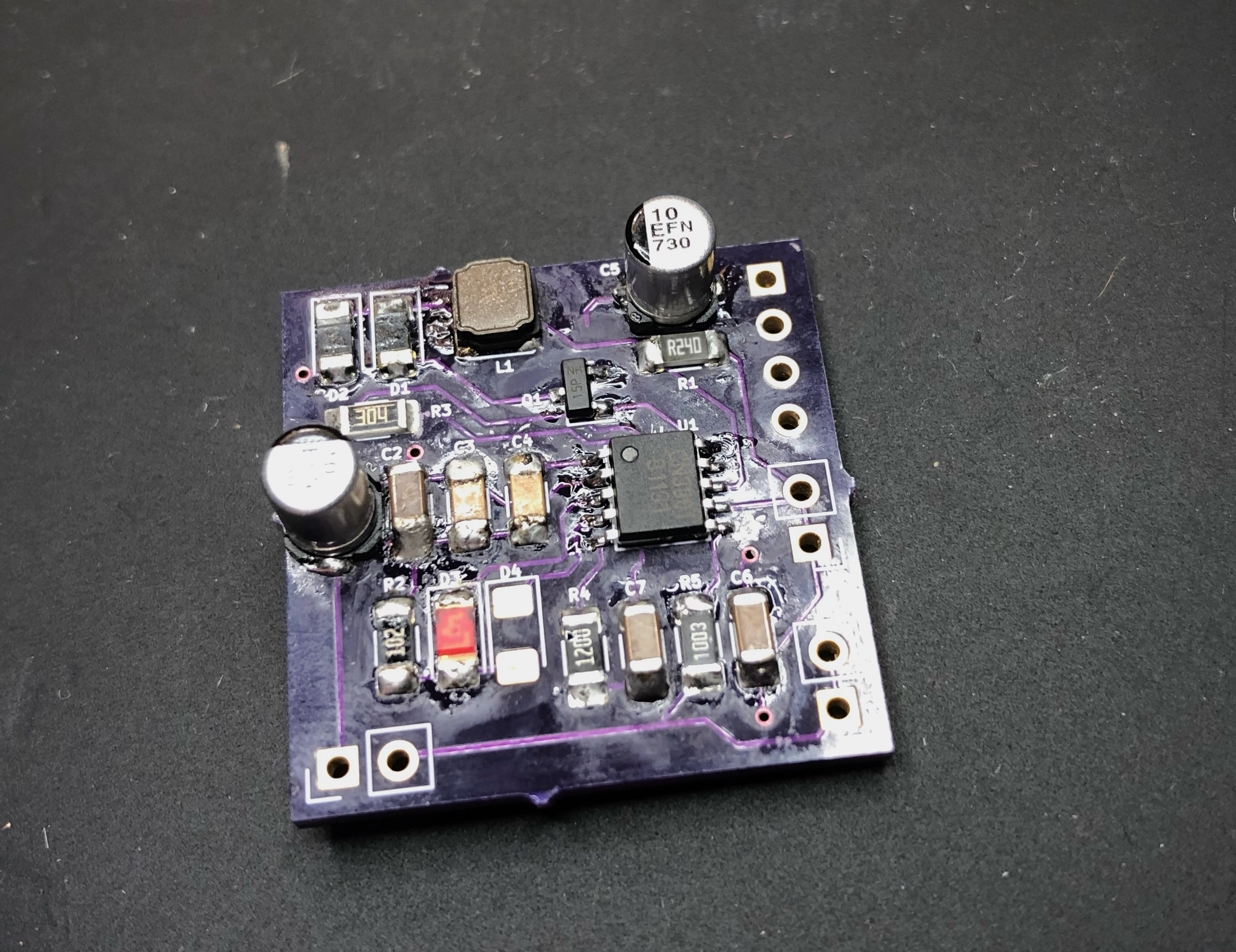
Here is the charging board, assembled with its external components:
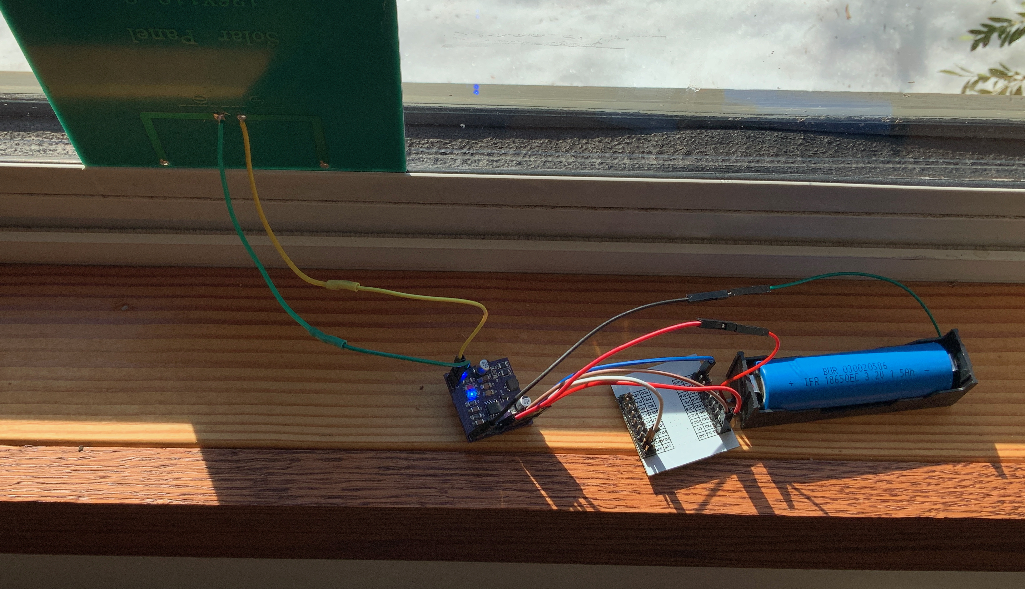
And here is the application, with the solar panel, charging board, ESP32, and 18650 LiFePo4 battery:
Note. This board is currently under development. If you are interested in building one of your own, please reach out at the contact instructions at the bottom of this page, as the design is currently in a state of flux.
Observations
With a 2 watt 6v solar panel and a 18650 LiFePo4 battery, this circuit seems pretty capably of running the ESP32 (with a chunk of sleep) indefinitely, while charging the battery during daylight hours.
Here, for example, is a sample run over 5 sunny days, with the ESP32 sleeping for 10 minute intervals, waking, taking an ADC reading, starting WiFi, and sending a status message over UDP to a server listing on my network:
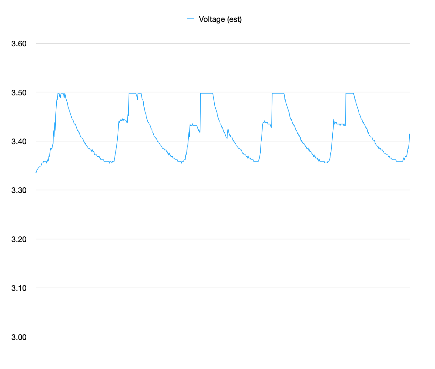
Note. The cap at 3.5 volts would appear to be an artifact of the ADC readings hitting a max value; however, spot testing with a volt meter suggests that the voltage readings are, in fact, correct (or at least close).
The circuit charges the battery to around 3.5 volts (as measured via the ADC circuit) while the sun is close to directly facing the solar panel, which in this case I had in a west-facing window. After sunset, the voltage would gradually decrease to a trough of around 3.35v. Not bad, and apparently sustainable, as long as there is plenty of sun!
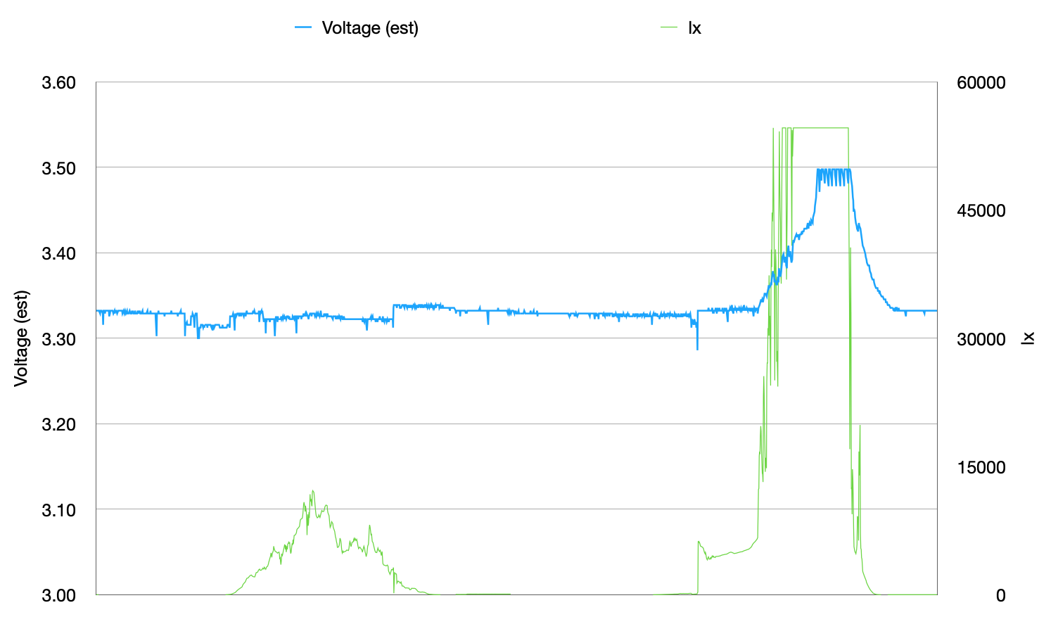
Surprisingly, the behavior is not terribly different if the sleep interval is reduced to 1 minute. In the following graph, I added a BH1750 luminosity sensor to read illuminance in lux over three sunny days:
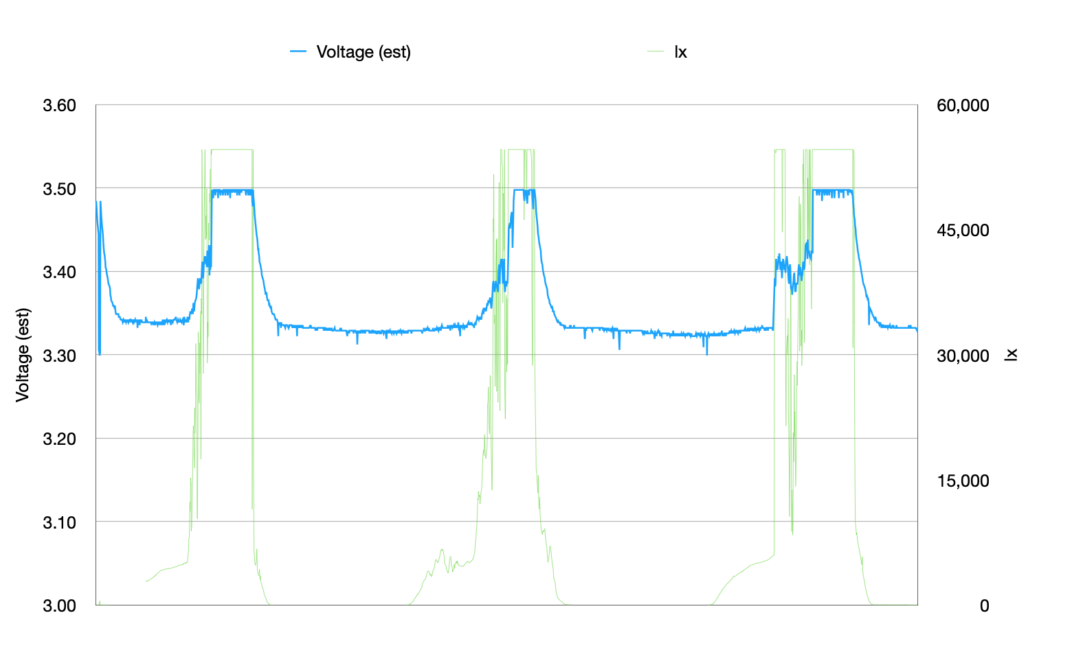
And of course on a cloudy, rainy day, we did not add much in the way of charge to the battery; however, we were able to make it through 2 days without even a brownout on the ESP32, so that 1.5Ah 18650 battery packed plenty of punch, to make it two whole days without a significant charge!
So far, I feel like I have a charging circuit that works well enough to power an ESP32 for an least an undetermined period of time, away from a power source. The real test will be to place it outdoors, in a weather-proof container, to see if it can survive under those conditions. I will have to wait for a while for a cold New England winter, but it will be interesting to see how well or if it will work later this summer, under high humidity and temperature conditions. We shall see!
Next time
Next time, I will talk about the software used to drive these experiments. Not surprisingly (for me), they are based on the AtomVM Erlang virtual machine, which runs on the ESP32 platform.
Copyright (c) 2021 dushin.net This work is licensed under a Creative Commons Attribution 4.0 International License.

Comments
If you have comments or questions about this blog post, please send me email using first-name -at- last-name -dot- net, where you can find my first and last name in the About page of this blog.
Hint to you ‘bots out there: It’s embedded in a picture. Have fun!