Running Micropython on the ESP8266
In the previous post in this series, I talked about how to get started with ESP8266 development on the Macintosh. In that post, we walked through building a basic development board with an ESP-01 (though only slightly modified instructions would also work with an ESP-12), and running some simple AT commands through the serial interface on the Macintosh, enabling some basic networking features of the ESP8266 in the process. In that post, we used only the ESP8266 functionality provided by the basic firmware image provided by Espressif, which is great for testing basic functionality. But what makes the ESP8266 exciting is the ability to program the chip to suite your own purposes. There is only so much useful you can do with AT commands. The real fun comes when you can run your own programs on the board.
In this blog post, I’d like to talk about how to image an ESP8266 with a different firmware image, notably, the MicroPython firmware. Using python as a development platform has some nice properties. Python is a mature language and is available on many platforms. It is a simple language with clear semantics, has nice integration with the underlying operating systems on which it runs, and makes a great platform for rapidly prototyping ideas. The MicroPython port to the ESP8266 is still undergoing development, but it is reaching a point of stability where it is pretty usable.
As in the previous blog post, this post is focused on development on the Macintosh platform. Most of the instructions are likely readily translatable to Linux, though perhaps not as readily to Windows. And like the previous blog post, this post will try to use as much of the command line as possible. I’ll assume a development board along the lines of the one described previously.
esptool
In order to read and write images from or to the ESP8266, we need to do a few things:
epstool.py python program.The epstool.py program is available on github, so we will first need to install git, using Homebrew on the Mac. Assuming Homebrew is installed, run the following from the Terminal:
shell$ brew install git
Once you have git installed, you can clone the esptool github repository. Find a suitable location, and run:
shell$ git clone https://github.com/themadinventor/esptool
Cloning into 'esptool'...
remote: Counting objects: 513, done.
remote: Compressing objects: 100% (15/15), done.
remote: Total 513 (delta 6), reused 0 (delta 0), pack-reused 498
Receiving objects: 100% (513/513), 284.30 KiB | 0 bytes/s, done.
Resolving deltas: 100% (273/273), done.
Checking connectivity... done.
This creates the esptool directory, which you can then cd into, and check out version 1.1 of the tool (the latest tagged version, at the time of writing):
shell$ cd esptool
shell$ git checkout v1.1
Note: checking out 'v1.1'.

You are in 'detached HEAD' state. You can look around, make experimental
changes and commit them, and you can discard any commits you make in this
state without impacting any branches by performing another checkout.

If you want to create a new branch to retain commits you create, you may
do so (now or later) by using -b with the checkout command again. Example:

  git checkout -b <new-branch-name>

HEAD is now at aff71ca... Bump version to v1.1
For there, you can then install the tool via the setup.py script in the esptool directory:
shell$ sudo python ./setup.py install
...
Finished processing dependencies for esptool==1.1
You should now have esptool.py installed in /usr/local/bin, which should be accessible from your PATH environment variable.
With esptool.py in your PATH, you can acquire some information about your ESP8266.
Connect the GP0 pin on your ESP8266 to the ground (-) rail on your breadboard, and issue the chip_id option to the esptool.py command, specifying the /dev/tty.SLAB_USBtoUART port:
shell$ esptool.py --port=/dev/tty.SLAB_USBtoUART chip_id
Connecting...
Chip ID: 0x0080d271
Note. I have had issues with running the esptool.py program repeatedly, where the first run of a command will run successfully after a reboot, but will fail a second or third time. I suspect it has something to do with the way I have wired the board, but I can work around the issue by rebooting the device whenever I need to run a command. It's a little inconvenient, but it works.
In order to proceed, we will need to get some information about the flash module on the ESP8266 module. (Think of the flash module as the equivalent of the ESP8266’s hard disk). If we get the flash_id, we can determine the manufacturer and model of the flash module on the board:
shell$ esptool.py --port=/dev/tty.SLAB_USBtoUART flash_id
Connecting...
Manufacturer: e0
Device: 4014
In this case, the manufacturer code is 0xE0 and the device ID is 0x4014, which some Googling tells me is Berg Micro, model BG25Q80A, which is a 1 megabyte flash module. You can find many flash chip codes here.
Backing Up
Knowing the flash size, we can make a backup of the original flash image by using the read_flash option to the esptool.py. The command takes a start address, the number of bytes (1 megabyte, or 1048576 bytes, in my case), and the name of the file to which you’d like to save the image.
shell$ esptool.py read_flash --help
usage: esptool read_flash [-h] [--no-progress] address size filename

positional arguments:
  address            Start address
  size               Size of region to dump
  filename           Name of binary dump

optional arguments:
  -h, --help         show this help message and exit
  --no-progress, -p  Suppress progress output
For example:
shell$ esptool.py --port=/dev/tty.SLAB_USBtoUART read_flash 0 1048576 /tmp/orig-esp8266-image.img
Connecting...
Please wait...
shell$ ls -l /tmp/orig-esp8266-image.img
-rw-rw-r--  1 me   wheel  1048576 Jul 17 19:16 /tmp/orig-esp8266-image.img
We now have a copy of the original ESP8266 image that came from the manufacturer. Don’t forget to back it up to a safe location!
MicroPython
MicroPython is a port of the Python programming language to various embedded devices and micro controllers. It features a stripped down version of Python, and supports numerous platforms.
Recently, there has been a kickstarter campaign to port MicroPython to the ESP8266.
In the remainder of this tutorial, we will install MicroPython on the ESP8266 and experiment with some of its features, analogously to the steps we took in the previous blog post using the AT commands available on the base firmware image.
You now have two choices for installing MicroPython on your ESP8266:
- The easy way, which is to simply install a pre-built binary image downloaded from the MicroPython web site;
- The hard way, which is to build from source.
We describe both steps below.
Installing MicroPython from Pre-built Images
In July of 2016, the ESP8266 MicroPython kickstarter project announced that it would start providing binary distributions of MicroPython firmware images for the ESP8266. Nightly builds are now available on their downloads page, with a promise to provide release versions, as well, as they become available.
Before proceeding, use the esptool.py command to erase the flash on your ESP866:
shell$ esptool.py --port=/dev/tty.SLAB_USBtoUART erase_flash
esptool.py v1.2-dev
Connecting...
Erasing flash (this may take a while)...
Note. I find that this command runs very quickly, and in fact if you look at the source code, it looks like esptool.py is making the ESP8266 do the erase from ROM.
Your ESP8266 should at this point no longer be bootable, but don’t worry! You have a backup. And we will now install MicroPython on the device.
Find the latest firmware image for the ESP8266 (I found esp8266-2016-07-20-v1.8.2-19-gc3f519a.bin, which is 19 commits past 1.8.2).
Then simply use esptool.py to upload the firmware to your ESP8266.
shell$ esptool.py --port=/dev/tty.SLAB_USBtoUART write_flash --flash_size=8m 0 /Users/me/Downloads/esp8266-2016-07-20-v1.8.2-19-gc3f519a.bin
Connecting...
Erasing flash...
Took 3.28s to erase flash block
Wrote 507904 bytes at 0x00000000 in 56.1 seconds (72.4 kbit/s)...

Leaving...
Note. Remember to move the GP0 pin on your ESP8266 to the negative/ground rail on your breadboard, in order to put the ESP8266 in flash mode.
You may need to adjust the flash_size parameter you use to esptool.py. Many ESP-12 boards come with 4 megabyte flashes. Note that flash_size is measured in megabits. So a for a 4 megabyte board, you would use --flash_size=32m.
Note. At the time of writing, I have had issues flashing the current MicroPython images on ESP-12 boards. The flashing works properly, but when I boot the ESP8266, MicroPython somehow fails to initialize the local FAT file system that is supposed to be available for writing MicroPython applications. Investigations are ongoing. See the ESP8266 MicroPython Forum for continuing updates.
Congratulations! If all went according to plan, you now have MicroPython installed on your ESP8266!
Building MicroPython for the ESP8266
Building MicroPython on the ESP8266 is a fairly involved process, but prior to July 2016, it was the only way to get an image (if you were not already a contributor to the kickstarter project). We are including instructions for building and installing a build firmware image here, but feel free to use the pre-built freeware images described above, if that’s easier.
The folks at Acrobatic have created a nice YouTube video on how to build MicroPython for the ESP8266, and on MacOS, no less! Instead of repeating all the instructions they provide in their video, I will just highlight the top level instructions with links for you to follow:
- Build the
esp-open-sdkby following the "Requirements and Dependencies" and "Building" sections of the README at https://github.com/pfalcon/esp-open-sdk (Note: I had to installhelp2manviabrew install help2manbefore running themakecommand.) - Pre-pend the Xtensa compiler from the
esp-open-sdktoolchain to yourPATHenvironment variable via:export PATH=/Volumes/case-sensitive/esp-open-sdk/xtensa-lx106-elf/bin:$PATH - Clone the MicroPython gitbup repo via:
git clone https://github.com/micropython/micropythonfrom the top level of thecase-sensitivefile system you created when your built theesp-open-sdk - Follow the "Build Instructions" section of the MicroPython for ESP8266 README in the MicroPython github repo, up to the
makeinstruction.
Note. I have had issues re-mounting thecase-sensitivefile system created as part of theesp-open-sdkbuild instructions. I can, however, mount this image read-write with the following command:hdiutil attach -owners on /path/to/images/case-sensitive.dmg -shadow
After following these instructions, you should have built firmware images in your build directory:
shell$ pwd
/Volumes/case-sensitive/micropython/esp8266
shell$ ls -l build/*.bin
-rw-rw-r--  1 me  staff  507584 Jul 19 18:55 build/firmware-combined.bin
-rw-rw-r--  1 me  staff   34896 Jul 19 18:55 build/firmware.elf-0x00000.bin
-rw-rw-r--  1 me  staff  470720 Jul 19 18:55 build/firmware.elf-0x09000.bin
You may then use the esptool.py command to erase the flash on your ESP866:
shell$ esptool.py --port=/dev/tty.SLAB_USBtoUART erase_flash
esptool.py v1.2-dev
Connecting...
Erasing flash (this may take a while)...
And then run make, specifying the port for the ESP8266 and the deploy target:
shell$ make PORT=/dev/tty.SLAB_USBtoUART deploy
Use make V=1 or set BUILD_VERBOSE in your environment to increase build verbosity.
Writing build/firmware-combined.bin to the board
esptool.py v1.2-dev
Connecting...
Running Cesanta flasher stub...
Flash params set to 0x0020
Writing 507904 @ 0x0... 507904 (100 %)
Wrote 507904 bytes at 0x0 in 44.2 seconds (91.9 kbit/s)...
Leaving...
Verifying just-written flash...
Verifying 0x7bec0 (507584) bytes @ 0x00000000 in flash against build/firmware-combined.bin...
-- verify OK (digest matched)
#@esptool.py --port /dev/tty.SLAB_USBtoUART --baud 115200 write_flash --flash_size=8m 0 build/firmware.elf-0x00000.bin 0x9000 build/firmware.elf-0x0[1-f]000.bin
Congratulations! You have just imaged your ESP8266 with a MicroPython image built from source!
Running MicroPython on the ESP8266
Now that you have MicroPython installed, we will now run the MicroPython runtime on the ESP8266.
Power down your ESP8266 and move the GP0 pin back to the positive (+) rail. Start the minicom program like we did before:
shell$ minicom -D /dev/tty.SLAB_USBtoUART
Welcome to minicom 2.7

OPTIONS:
Compiled on Jun  8 2016, 16:10:27.
Port /dev/tty.SLAB_USBtoUART, 22:13:46

Press Meta-Z for help on special keys
Power on the ESP8266, and you should see:
????pc$`??l?
could not open file 'main.py' for reading

#4 ets_task(4010035c, 3, 3fff62f0, 4)
MicroPython v1.8.2-19-gc3f519a on 2016-07-19; ESP module with ESP8266
Type "help()" for more information.
>>>
The “>>>” is the python prompt, which is running on the ESP8266. Enter a python expression:
>>> 1 + 2
3
The ESP8266 just evaluated 1 + 2. A true geek finds that interesting.
You may have noticed that unlike the AT commands we played with in the previous blog post, you do not need to manually send a line feed via ctl-j. You can even use the arrow keys to scroll back to (8) previous lines in the python shell!
At this point, we can do all of our programming on the ESP8266. The reference documentation for MicroPython on the ESP8266 is the best source of information for the kinds of thing you can do with python on this device, but we’ll play with a few commands that provide the same functionality as the steps we went through in the previous blog post. That should give you a sense of a small slice of what you can do in this environment. This part of the tutorial presumes some familiarity with the Python programming language, and is largely lifted from parts of the tutorial provided in the MicroPython documentation.
To start, we need to import the network module into our shell. We can then get a reference to the station mode WLAN, which will give us access to functions that configure the ESP8266 in station mode:
>>> import network
>>> sta_if = network.WLAN(network.STA_IF)
The sta_if identifier is now the object on which we will call functions.
As before, we can activate the station mode of the ESP8266 as follows:
>>> sta_if.active(True)
mode : sta(5c:cf:7f:80:d2:71) + softAP(5e:cf:7f:80:d2:71)
#5 ets_task(4020e33c, 28, 3fff7ae8, 10)
add if0
You can now scan for available networks via the scan operation:
>>> sta_if.scan()
scandone
[(b'MyWirelessNetwork', b'\x90\x84\r\xe0\xbc+', 11, -35, 4, 0)]
Note. I have had issues in the current implementation of MicroPython in getting all of the accessible networks.
Given a network, we can now attach to it:
>>> sta_if.connect('MyWirelessNetwork', 'XXXXXXXXXXXXXX')
f r0, >>> scandone
state: 0 -> 2 (b0)
state: 2 -> 3 (0)
state: 3 -> 5 (10)
add 0
aid 1
cnt

connected with MyWirelessNetwork, channel 11
dhcp client start...
chg_B1:-40
ip:192.168.1.178,mask:255.255.255.0,gw:192.168.1.1
Note. Thesta_if.activeandsta_if.connectfunctions are "sticky", in the sense that the modifications these functions cause are written to the flash memory on the device and will be preserved on the next reboot. Be sure to read the security warnings described in the previous blog post.
And we can check if it connected, and programmatically get information about how the network is configured:
>>> sta_if.isconnected()
True
>>> sta_if.ifconfig()
('192.168.1.178', '255.255.255.0', '192.168.1.1', '192.168.1.1')
Now that the ESP8266 is connected to the network, we can ping the it from the Mac in a separate window:
shell$ ping -c 10 192.168.1.178
PING 192.168.1.178 (192.168.1.178): 56 data bytes
64 bytes from 192.168.1.178: icmp_seq=0 ttl=255 time=5.264 ms
64 bytes from 192.168.1.178: icmp_seq=1 ttl=255 time=2.905 ms
64 bytes from 192.168.1.178: icmp_seq=2 ttl=255 time=3.846 ms
64 bytes from 192.168.1.178: icmp_seq=3 ttl=255 time=2.732 ms
64 bytes from 192.168.1.178: icmp_seq=4 ttl=255 time=5.380 ms
64 bytes from 192.168.1.178: icmp_seq=5 ttl=255 time=3.733 ms
64 bytes from 192.168.1.178: icmp_seq=6 ttl=255 time=2.887 ms
64 bytes from 192.168.1.178: icmp_seq=7 ttl=255 time=2.185 ms
64 bytes from 192.168.1.178: icmp_seq=8 ttl=255 time=2.170 ms
64 bytes from 192.168.1.178: icmp_seq=9 ttl=255 time=2.766 ms

--- 192.168.1.178 ping statistics ---
10 packets transmitted, 10 packets received, 0.0% packet loss
round-trip min/avg/max/stddev = 2.170/3.387/5.380/1.098 ms
As in the previous blog post, we can start the netcat utility in a separate window on the Mac:
shell$ netcat -l -v -p 44404
Note. Don't forget to temporarily disable the firewall on your Mac!
In order to connect to our netcat server, we will need to import the socket module, and construct an address structure using the getaddrinfo function:
>>> import socket
>>> addr_info = socket.getaddrinfo("192.168.1.154", 44404)
>>> addr = addr_info[0][-1]
>>> addr
('192.168.1.154', 44404)
This gives us a tuple, which we can then feed into a socket object to establish a connection:
>>> s = socket.socket()
>>> s.connect(addr)
In the netcat window, you should see
Connection from 192.168.1.178:25477
We can send some data like we did before:
>>> s.send('hello')
5
and you should see “hello” printed to the netcat window.
Finally, you can close the connection using the socket’s close function:
>>> s.close()
You should see the netcat utility then terminate in the other window.
Going Completely Wireless
So far, we have been communicating with the ESP8266 over the serial/UART interface. This is useful for development, but it can be inconvenient.
Fortunately, MicroPython ships with a web service, webrepl, you can use to communicate with the ESP8266 over the wireless network. This service uses web sockets, and is driven through a Web UI you can run directly in your browser.
On development builds, the webrepl service is not enabled by default, but you can enable it though the serial interface, as follows:
>>> import webrepl_setup
WebREPL daemon auto-start status: disabled

Would you like to (E)nable or (D)isable it running on boot?
(Empty line to quit)
> E
To enable WebREPL, you must set password for it
New password (4-9 chars): ****
Confirm password: ****
Changes will be activated after reboot
Would you like to reboot now? (y/n)
Enter y to reboot the device. When the device comes back up, the webrepl application should be running.
Note that the web sockets endpoint is listening on two networks, both the access point network the ESP8266 is running in router mode (192.168.4.1), and the station mode network the ESP8266 is running when connected to your network (192.168.1.178).
Open a browser window and connect to http://micropython.org/webrepl/ (I have tested this on both Chrome and Safari.)
Change the URL in the browser window to the address of your ESP8266 on the network (e.g., ws://192.168.1.178:8266/), and click connect. You will be prompted for the password you used to set up webrepl. Once you enter it correctly, you should then have access to the python shell:
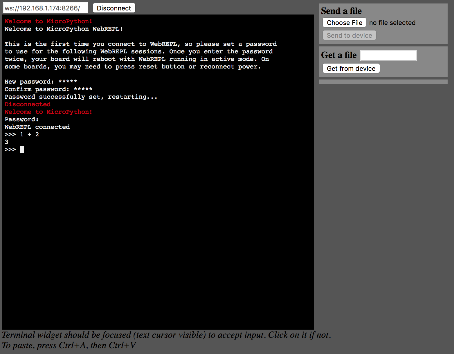
Restoring from a Backup
Finally, if you want to restore your ESP8266 back to its condition before we installed the MicroPython image, you can use the esptool.py command to write the image we created in the beginning of this tutorial back onto the ESP8266:
shell$ esptool.py --port=/dev/tty.SLAB_USBtoUART write_flash --flash_size=8m 0 /tmp/orig-esp8266-image.img
Resources
Here are some Micro Python related web sites I find myself visiting often for information:
- Micropython on ESP8266 documentation
- Micropython Firmware download page
- Micropython on ESP8266 Forum
Next Time
This tutorial has shown you how to install MicroPython on your ESP8266 and configure it so that it can connect to your wireless network and you can connect to the MicroPython shell on the device over a web interface, with no wires! (Other than power, of course)
Next time, we’ll experiment with some things we can do with the ESP8266 and MicroPython to connect to a simple sensor device (a temperature and humidity sensor), and to send that data to a listening service, for a true IoT use-case!
Copyright (c) 2016 dushin.net This work is licensed under a Creative Commons Attribution 4.0 International License.

Comments
Because of the prevalence of automated spam on the internet, I turn off comments on my blog posts. If you have comments or questions about this, please send me email using first-name -at- last-name -dot- net, where you can find my first and last name in the About page of this blog.